CPU P2CDS-622
Introduction
The P2CDS-622 CPU is based on a 600MHz ARM A5 core and is built upon the Green Hills Software “INTEGRITY” Real-Time Operating System (RTOS)
The INTEGRITY RTOS is built around a partitioning architecture to provide embedded systems with total reliability, optimal security, and maximum real-time performance,
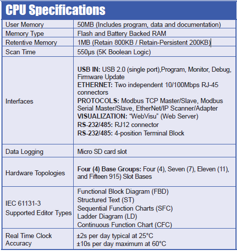
Specifications
Tip
A complete CPU datasheet can be downloaded here:
P2CDS-622 Datasheet
General System Specs

CPU Specific Specs
Danger
The CPU can NOT be removed or inserted while power is being applied!
Functionality
RUN/STOP Switch
This switch puts the CPU in Run mode (executing the program) or in a halted Stop mode.

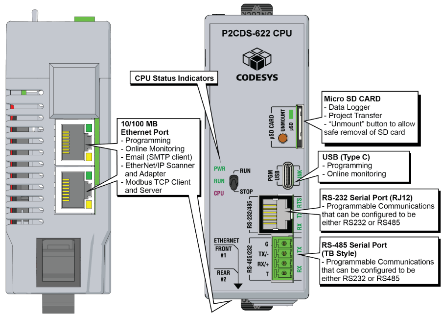
CPU Status Indicators
The following LEDs indicators next to the switch are used to display the states of the CPU:
PWR - CPU has power applied to it. Green = Powered, Off = Unpowered.
RUN - CPU is in “Run” mode (executing the program tasks). Green = Run, Off = Stopped.
CPU - CPU is in a reset condition or watch-dog timeout has occurred (Red) . Off = Normal operation.
Micro SD Card/Unmount Button
The SD Card can be used for Data Logging in the project.
When an SD Card is inserted, the “uSD” LED will flash green a few times then stay on steady green.
The “Unmount” button is pressed prior to removing the SD Card. When pressed, the uSD LED will flash momentarily during the unmounting process. When the uSD LED turns off, this indicates it is safe to remove the SD Card.

For technical specifications of the Memory Card refer to the section SD Card Usage.
USB - Type C
This is a standard USB-C Slave input for programming and online monitoring, with built-in surge protection.
The transfer rate is 480Mbps.

LINK - USB connection status. Green LED illuminated when connected (LINK established).
Ethernet
There are two (2) 10/100MB Ethernet ports located on the bottom of the CPU that are run independently from each other.
See- Ethernet for more information on how to configure the Ethernet ports.
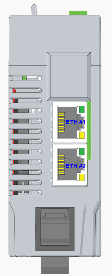
Bottom View of CPU
The RJ-45 pinout is shown below:

The section in CPU Communications entitled Ethernet describes these ports in more detail and how to configure them in the CODESYS IDE.
Tip
There is automatic crossover detection of which cable is inserted, so either cable will work.
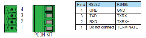
RS-485 Serial Port (TBLK)
The 4-position Terminal Block shown below supports RS-485 communications and is detailed in the section CPU Communications under Serial RS-232/RS-485.
RS-232 Serial Port (RJ-12)
The RJ-12 connector is shown below and supports RS-232 or RS-485 communications (selected within the CODESYS IDE) and is detailed in the section CPU Communications under Serial RS-232/RS-485.

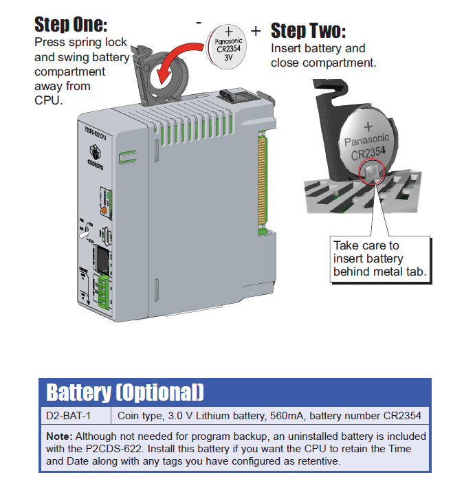
Battery
The Battery-backed SRAM is supplied the backup power via a coin cell battery in the unit as shown below.
Tip
There is a Super-Cap device that backs up the SRAM data when the Battery is removed. The backup time is a minimum of 8 hours with no loss of SRAM data.