Modbus RTU - Master Mode
The Modbus RTU protocol uses a Client/Server (Master/Slave) architecture for data exchange. It utilizes the P2CDS-622 Serial Ports (RS-232 or RS-485 configurable).
Clients (Masters) are devices that initiate any data exchange with other devices on the network. This applies to both I/O communications and service messaging.
The communication parameters such as the settings of the serial ports (baud rate, port number), are predefined in the configurator, for example the settings of the serial ports (baud rate, port number). Modbus commands are defined in the configurator and are oriented to a specific Modbus slave.
The commands are processed by the device at specific intervals, or can be triggered programmatically. For predefined commands, I/O channels are generated automatically with variables that can be mapped (I/O mapping).
Our example here will illustrate the setup parameters for the Serial port and a few Modbus commands defined for the channels.
Introduction
This project will utilize the Modbus RTU fieldbus device in the Master mode topology and requires a Modbus Slave device to be connected to the applicable Serial port.
Serial #1 is the RJ-12 connector, while Comm port #2 is the 4-pin Terminal Block (TBLK) connector.
The P2CDS-622 Intro project will default to using the four(4) slot Base P2-04B unit. If your system has a different Base, this can be changed within your project.
The main purpose for this example is to introduce you to the Modbus RTU Fieldbus configuration and setup.
System Requirements and Installation
- This section requires the following:
P2CDS-622 CPU
P2000 Base (any variant)
P2000 PowerSupply (any variant)
Latest version of CODESYS installed on Host PC
Recommendation for Data Protection
In order to minimize the risk of data security breaches, we recommend the following organizational and technical measures for the system that will run your applications:
Whenever possible, avoid exposing PLCs and controller networks to public networks and Internet.
Use additional data link layers for protection, such as a VPN for remote access, and install firewall mechanisms.
Restrict access to authorized persons only, and change any existing default passwords during the initial commissioning, and change them regularly.
If you want to publish a web visualization, then we strongly recommend utilizing HTTPS and assigning a simple password protection to prevent access to the functionality of your PLC over the Internet.
Help
Help is provided in the Help menu, as well as the context-sensitive <F1> key when in the IDE whether a project is open or not..
Currently, the web-based online help opens by default. This can be disabled in the CODESYS options so that the offline help (CHM format) is used.
Installation of Additional Software/Tools
To emulate an attached Modbus Slave, you can use a Modbus simulator tool like “ModRSsim2”.
This is located at: Modbus Simulator Utility and needs to be installed.
Note
If this tool is unavailable, there are other Modbus emulation tools that should suffice.
Creating a Project
Caution
To do this project, the steps outlined in the previous section Preparation have to be completed successfully.
When creating a project, the main items that need to be done initially are to install the target device’s (P2CDS-622) Package and pick the language that the program file will use.
The project can be made up of many program/design PRG files. These are referred to as Programmable Object Units or POUs.
Start CODESYS and Create a Project
Start CODESYS
(1). Start CODESYS from the Start menu (by default, the path is Programs > CODESYS (version).
You can also click the CODESYS icon that is located on the desktop after installation.
Create a project
(6). Click File > New Project
The example project here will be named ExampleRtu.
(7). In the New Project window, in the Templates section, select the Standard Project template.
(8). Specify a name and a storage location for the project and click OK
The project opens in the CODESYS Standard Project frame window.
(9). In the Device drop-down location, select the P2CDS622 device.
The next step will be to define the language for the initial program you will create (default name is PLC_PRG).
(10). In the PLC_PRG in drop-down location, select your programming language of choice e.g. Structured Text (ST).
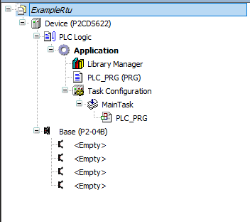
Your Project Tree view should look something like below with the Name of your project and the associated Device (P2CDS622) as the target.
The default Base (P2-04B) is inserted in the tree with no modules added yet, i.e. <Empty>. If your hardware topology is a different Base, see the section below on changing the Base type.
The elements of the project tree can be investigated further by going to the Help section online by pressing <F1> in the device tree area and searching for a specific item of interest.
Add Modbus-Serial Fieldbus
For this example configuration, we will use the RS-485 electrical interface over the 4-pin Terminal Block (Port2) Comm port.
(11). Right -click on Device (P2CDS622) and select Add Device > Fieldbuses > Modbus > Modbus Serial Port > Modbus COM
Configure the Serial Port
Note
RJ-11 connector corresponds to Serial Com port #1, 4-pin TBLK is Serial Com port #2.
To assign the Comm Port to “2”, setup the Baud Rate, etc. for this device,
(12). Double-click on the Modbus_COM device just added.

To assign the Comm Port as a RS-485 type interface,
(13). Double-click on the Device (P2CDS622) in the device tree and look for Settings: Serial Port Parameters.
(14). In drop down for Value in the TB Serial section, select as shown:
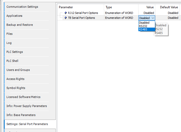
No other settings here to change.
Add Modbus-Serial MASTER Type
(15). Right -click on Modbus_COM and select Add Device > Fieldbuses > Modbus > Modbus Serial Master > Modbus Master, COM Port
Configure the Master
(16). Double-click on the Modbus_Master_COM device just added and select RTU and any other parameters under General you want.
Note
No other tabs e.g. ModbusGeneric.. are to be modified.
Add Modbus-Serial SLAVE Type
(17). Right -click on Modbus_Master_COM and select Add Device > Fieldbuses > Modbus > Modbus Serial Slave > Modbus Slave, COM Port
Tip
There is a downloadable example project in the Modbus TCP-Master Mode section that may be a further help for Channel Function setup. See- ModbusTCP project
Configure the Slave
(18). Double-click on the Modbus_Slave_COM device just added modify parameters as desired under General you want.
- General
Slave address (1..247) - Address of a serial Modbus device (value between 1 and 247).
Response timeout (
ms value) - Maximum time (in milliseconds) to wait Time interval for the master to wait for the response from a slave node. This is configured especially for this slave node and overwrites the general response timeout setting of the respective master.
Modbus Slave Channel
Each Modbus Channel needs to have its data exchanges specifically defined.
(19). Click on the lower right hand button named Add Channel… setup the channels in your project as desired.
Channel - Name (
text) - optional string for naming the channel.Channel - Access Type (
type) - type of Modbus request by Function Code (FC).
Read Coils - (FC 1)
Read Discrete Inputs - (FC 2)
Read Holding Registers - (FC 3)
Read Input Registers - (FC 4)
Write Single Coil - (FC 5)
Write Single Register - (FC 6)
Write Multiple Coils - (FC 15)
Write Multiple Registers - (FC 16)
Read/Write Multiple Registers - (FC 23)
Channel - Trigger (
type) - when the request is to occur.
Cyclic - request occurs periodically.
Rising Edge - The request occurs as a reaction to a rising edge of the Boolean trigger variables. The trigger variable is defined on the I/O Mapping tab.
Application -The Modbus request is triggered by the PLC application. This happens by means of the ModbusChannel function block (Explicit mode).
Channel - Cycle time (
ms value) - Request interval for a Cyclic. Should be the same as or a multiple of the application cycle time.Channel - Comment (
text) - Description of the channel.READ Register - Offset (
0-65535) - Start address where reading should start (value range 0–65535).READ Register - Length (
value) - Number of registers to be read (for word access) or number of discrete inputs to be read (for bit access).READ Register - Error Handling (
type) - If communication error, should previous data be kept (Keep…) or set to 0 (Set…).WRITE Register - Offset (
0-65535) - Start address where writing should start (value range 0–65535).WRITE Register - Length (
value) - Number of the register to be written to (value range 0–65535) .
- Modbus Slave Init
You use this tab to define initialization commands. Initialization commands are executed one time when starting the bus or activating the slave (setting the “Enabled” flag of the slave instance). When setting up or editing a slave initialization value, the following parameters are available in the respective dialogs:
Move Up, Move Down - the order of initialization.
New - opens the Initialization Value dialog. The initialization commands are defined.
Access Type (
Write FC) - applicable Write Function Code (FC 05, FC 06, FC 15 or FC 16) to perform.Register Offset (
0-65535) - actual number of the register to be written to (value range 0–65535).Length (
value) - total number of registers to be written to (= words). The value range of the parameter depends on function code.Initialization (
value) - initialization value for the register.Comment (
text) -short description of the data.
- ModbusGenericSerialSlaveParameters
( Do not modify )
These reflect any settings that have been made previously.
- ModbusGenericSerialSlave IEC Objects
( Do not modify )
Tip
There is a downloadable example project in the Modbus TCP-Master Mode section that may be a further help for Channel Function setup. See- ModbusTCP project
Closing Comments
At this point you should be ready to write your specific application code.
Additional features like edge triggered enabling are available.
Help can be found at Modbus Help