Thermocouple Input Module
This example project utilizes the eight(8) channel Thermocouple Temperature module- P2-08THM.
Datasheets, specifications and setup for the module can be found here- Thermocouple Module
Introduction
The P2-08THM Thermocouple Input Module provides eight differential channels for receiving thermocouple and voltage input signals.
The main purpose for this project is to introduce you to a P2-08THM Module and its associated configuration, data flow and status signals.
System Requirements and Installation
- This section requires the following:
P2CDS-622 CPU
P2000 Base (any variant)
P2000 PowerSupply (any variant)
P2-08THM Temperature Module
Latest version of CODESYS installed on Host PC
Note
If Ethernet ports are not configured, see Refer to section Ethernet.
Recommendation for Data Protection
In order to minimize the risk of data security breaches, we recommend the following organizational and technical measures for the system that will run your applications:
Whenever possible, avoid exposing PLCs and controller networks to public networks and Internet.
Use additional data link layers for protection, such as a VPN for remote access, and install firewall mechanisms.
Restrict access to authorized persons only, and change any existing default passwords during the initial commissioning, and change them regularly.
If you want to publish a web visualization, then we strongly recommend utilizing HTTPS and assign a simple password protection to prevent access to the functionality of your PLC over the Internet.
Help
Help is provided in the Help menu, as well as the context-sensitive <F1> key when in the IDE whether a project is open or not.
Currently, the web-based online help opens by default. This can be disabled in the CODESYS options so that the offline help (CHM format) is used.
Caution
To do this project, the steps outlined in the previous section Preparation have to be completed successfully.
Create a Project
When creating a project, the main items that need to be done initially are to install the target device’s (P2CDS-622) Package and pick the language that the program file will use.
The project can be made up of many program/design PRG files. These are referred to as Programmable Object Units or POUs.
Start CODESYS and Create a Project
Start CODESYS
(1). Start CODESYS from the Start menu (by default, the path is Programs > CODESYS (version).
You can also click the CODESYS icon that is located on the desktop after installation.
Create a project
(2). Click File > New Project
The example project here will be named Demo_P208THM
(3). In the New Project window, in the Templates section, select the Standard Project template.
(4). Specify a name and a storage location for the project and click OK
The project opens in the CODESYS Standard Project frame window.
(5). In the Device drop-down location, select the P2CDS622 device.
The next step will be to define the language for the initial program you will create (default name is PLC_PRG).
(6). In the PLC_PRG in drop-down location, select language of choice. In this example we chose Structured Text (ST).
Your Project Tree view should look something like below with the Name of your project and the associated Device (P2CDS622) as the target.
The default Base (P2-04B) is inserted in the tree with no modules added yet, i.e. <Empty>. If your hardware topology is a different Base, see the section below on changing the Base type.
The elements of the project tree can be investigated further by going to the Help section online by pressing <F1> in the device tree area and searching for a specific item of interest.

Add Fieldbus
(Not applicable for this project. Refer to section Ethernet for more information if desired. )
Change Base Type (if req’d)
If you are using a Base topology other than the P2-04B, you can change it now.
(7). In the device tree, highlight with a single click the Base (P2-04B) element, then Right-click. Select Plug Device.
The Plug Device dialogue box should appear.
(8). Under the Miscellaneous name, find the Base unit device you want and double-click. Close the box.
The updated Base should be showing.
Add the IO Module P2-08THM
The IO Module will be pulled from the Device Library and inserted into Slot 1 of the Base (P2-04B).
(9). In the device tree, below the Base (P2-04B) element, in the top slot (Slot 1), highlight it with a single click, then Right-click. Select Plug Device.
The Plug Device dialogue box should appear.
(10). Under the Miscellaneous name, find the P2-08THM device and double-click on it and close the box.
The module should now appear in the first Slot of the Base.
Configure the Module
This can be done at any time during the project design.
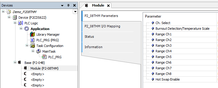
(11). Double-click on the P2-08THM module in the P2-04B device tree.
There are two main areas that require configuration- the Parameters section (number of channels, channel sensor type, etc.) and the I/O Mapping section which defines the variable names for the channels and status data.
A View of the Module
The parameters that require configuration and the associated status signals are defined in the IO Module Configuration section (P2-08THM)- Configuration
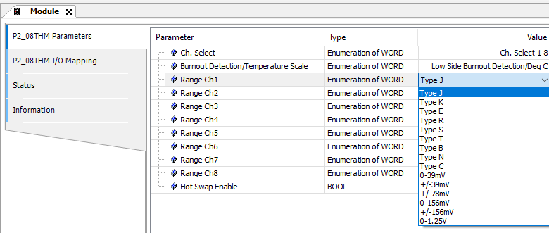
Parameters
This section defines the Channel’s Sensor type- Thermocouple or Voltage and associated range.
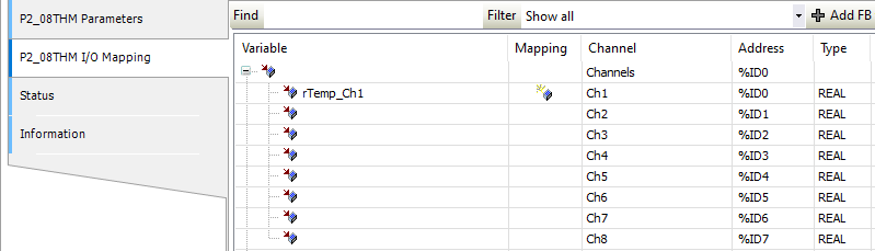
IO Mapping
The IO Mapping area is where the user defines the variable names for the Input channel data and any associated Status signals they may want to monitor.
Channel Input Data
The data coming in on channel one is named rTemp_Ch1. This is a Global here, but you can also reference a variable assignment within your project by assigning that exact variable name in this section.
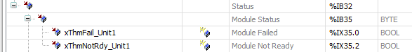
Status - General
This indicates the overall Module status.
This includes if the Module has a fatal error Module_Failed or if there is valid data present based on the latest configuration settings Module Not Ready.
Status - Channel
This indicates if the Thermocouple sensor has failed (burned out and open).
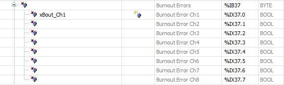
This indicates if the channel is Over or Under the max/min range for the sensor type selected.

Create the Main Program
Tip
For Project Creation, Execution and Debugging refer to example in Analog Input Project.