Modbus TCP - Master Mode
The Modbus TCP protocol uses a Client/Server (Master/Slave) architecture for data exchange.
Our example here is for a Modbus TCP implicit (cyclic) mode with data exchanges being managed by the Modbus TCP IOScanner. The Modbus TCP IOScanner is a service in the Device library that is based on Ethernet that polls slave devices continuously to exchange data, status, and diagnostic information.
For example, this is lieu of having specific (Explicit mode) Function Blocks in your program that generates the Modbus commands/data exchanges on demand.
This process monitors inputs and controls outputs of slave devices.
Clients (Masters) are devices that initiate any data exchange with other devices on the network. This applies to both I/O communications and service messaging.
The communication between the Modbus TCP IOScanner and the slave device is accomplished using Modbus TCP channels which are discussed in detail later.
Introduction
This project will utilize the Modbus TCP fieldbus device in the Master mode topology and requires a Modbus Slave device to be connected to the applicable Ethernet port.
The Slave device will be emulated using a Modbus TCP software application on a PC.
The P2CDS-622 Intro project will default to using the four(4) slot Base P2-04B unit. If your system has a different Base, this can be changed within your project.
The programming language chosen for this project will be “Structured Text”.
The main purpose for this project is to introduce you to the Modbus TCP Fieldbus and some Function Codes examples.
System Requirements and Installation
- This section requires the following:
P2CDS-622 CPU
P2000 Base (any variant)
P2000 PowerSupply (any variant)
Latest version of CODESYS installed on Host PC
Modbus Slave Simulator or Modbus Slave Device attached Example used in this project is “ModRSsinm2” found at: Modbus Simulator
Familiarity with the “Structured Text” programming language.
Recommendation for Data Protection
In order to minimize the risk of data security breaches, we recommend the following organizational and technical measures for the system that will run your applications:
Whenever possible, avoid exposing PLCs and controller networks to public networks and Internet.
Use additional data link layers for protection, such as a VPN for remote access, and install firewall mechanisms.
Restrict access to authorized persons only, and change any existing default passwords during the initial commissioning, and change them regularly.
If you still want to publish your web visualization, then we strongly recommend that you assign it at least a simple password protection to prevent access to the functionality of your PLC over the Internet.
Help
Help is provided in the Help menu, as well as the context-sensitive <F1> key when in the IDE whether a project is open or not.
Currently, the web-based online help opens by default. This can be disabled in the CODESYS options so that the offline help (CHM format) is used.
Caution
To do this project, the steps outlined in the previous section Preparation have to be completed successfully.
Installation of Additional Software/Tools
To emulate an attached Modbus Slave, we will use a Modbus simulator tool- “ModRSsinm2”.
This is located at: Modbus Simulator and needs to be installed.
Note
If this tool is unavailable, there are other Modbus emulation tools that should suffice.
Creating a Project
When creating a project, the main items that need to be done initially are to install the target device’s (P2CDS-622) Package and pick the language that the program file will use.
The project can be made up of many program/design PRG files. These are referred to as Programmable Object Units or POUs.
Tip
NOTE: Below is a link to the completed project that can be downloaded entitled Demo_ModbusTcpMaster. The following instructions on this page provide details to the generation of this project.
Download the project here: Modbus TCP project
Start CODESYS and Create a Project
Tip
The following steps are for a guide to show you how to create your own project in lieu of the completed Demo project.
Start CODESYS
(1). Start CODESYS from the Start menu (by default, the path is Programs > CODESYS (version).
You can also click the CODESYS icon that is located on the desktop after installation.
Create a project
(6). Click File > New Project
The example project here will be named ExampleProj1.
(7). In the New Project window, in the Templates section, select the Standard Project template.
(8). Specify a name and a storage location for the project and clock OK
The project opens in the CODESYS Standard Project frame window.
(9). In the Device drop-down location, select the P2CDS622 device.
The next step will be to define the language for the initial program you will create (default name is PLC_PRG).
(10). In the PLC_PRG in drop-down location, select Structured Text (ST). This will be the language we will use for the first program.
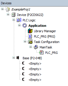
Your Project Tree view should look something like below with the Name of your project and the associated Device (P2CDS622) as the target.
The default Base (P2-04B) is inserted in the tree with no modules added yet, i.e. <Empty>. If your hardware topology is a different Base, see the section below on changing the Base type.
The elements of the project tree can be investigated further by going to the Help section online by pressing <F1> in the device tree area and searching for a specific item of interest.
Caution
If Ethernet ports have not been configured yet, it is required that they be setup per section Ethernet !
Add NetConfig
(11). Add this device as outlined in the section Ethernet.
Add Fieldbus
The Modbus TCP device will reside under the Ethernet device in the Device Tree. The first step is to add an Ethernet device in the project.
Add Ethernet Device
(12). Right Click on Device (P2CDS622) in the Device Tree and in the drop-down select Add Device. In the Add Device pop-up dialog box, Expand Ethernet, and select Ethernet Adapter. Double-click on Ethernet and this should add the Ethernet device to the Device Tree.
Assign/Configure Ethernet Device
(13). Select the correct Ethernet port for this device by double-clicking on the Ethernet device and under the General > Network interface option area, browse to the applicable interface to use or you can define a custom IP Address, etc. by selecting the Adjust operating system settings and filling in accordingly.
Caution
The Adjust operating system settings is not recommended for most applications. This will override the settings for the Ethernet port that were defined in the setup with the NetConfig device and may cause undesired behavior for the Ethernet fieldbus port.
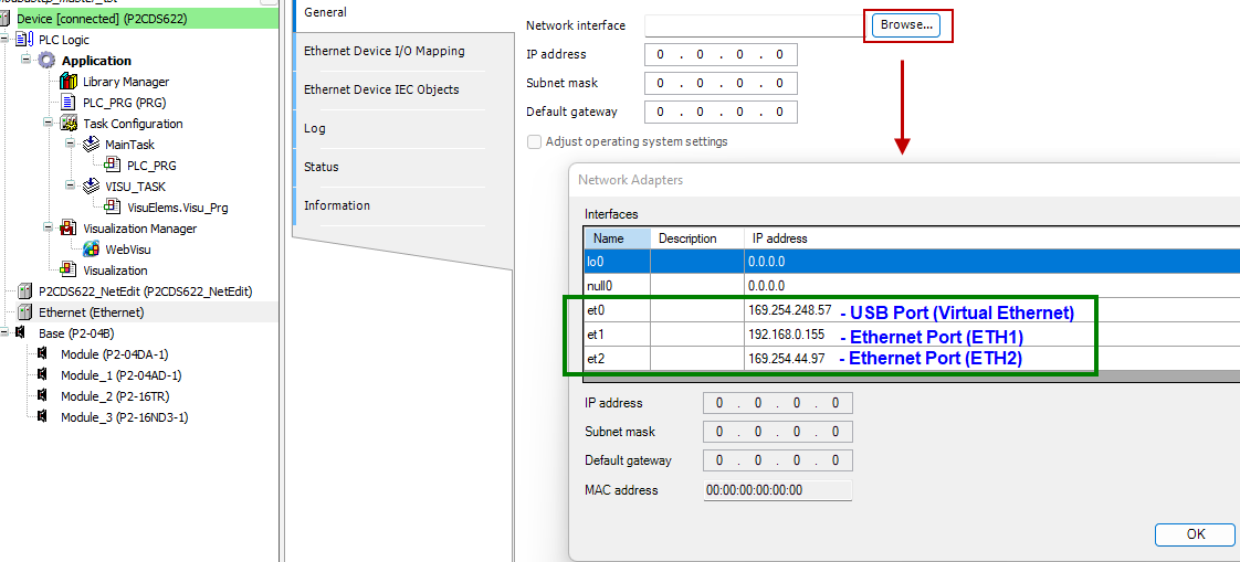
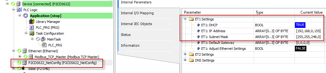
To verify that the assigned Ethernet Device IP address matches the Ethernet port, when the IDE is connected to the PLC and Logged in, you should see a IP address match.
For example the IP address of Ethernet port #1 (ET1) matches at 192.168.0.155.
Add Modbus-TCP Master
The Modbus TCP Master function will be assigned to this Industrial Ethernet channel.
(14). Right Click on Ethernet (Ethernet) and in the Device Tree drop-down select Add Device. In the Add Device pop-up dialog box, Expand Fieldbusses, expand Modbus, expand Modbus_TCP_Master. Double-click on Modbus_TCP_Master and this should add the Ethernet device to the Device Tree.
Configure Modbus-TCP Master
(15). In the Modbus_TCP_Master section, update any configuration parameters in the sections highlighted below.
- General
Response timeout (
ms value) - Time interval (in milliseconds) for the master to wait for the response from a slave node.If the nodes do not respond within this time span, then an error is issued for the implicit slave function block. The value specified for the time span is also the default value for each node. For each node, you can still set a specific value within its Modbus TCP slave configuration.
Socket timeout (
ms value) - Maximum time (in milliseconds) to wait for incoming TCP/IP packagesThe bus cycle task can be blocked during this time. (Example: When a Modbus TCP slave is disconnected)
- Modbus TCPMaster I/O Mapping
Bus Cycle task (
task) - Task associated with executing the Modbus cyclic data exchange.
- Modbus TCPMaster IEC Objects
( Do not modify )
- Modbus TCPMaster Parameters
ExtendedChannelConfig - (not modifiable).
OptimizationOn - (not utilized, Vendor specific).
SocketTimeout (
ms value) - value reflects what was set in General > Socket timeout item.ResponseTimeOut (
ms value) - value reflects what was set in General > Response timeout item.AutoReconnect - (
TRUE,FALSE) - auto confirm connection error and reconnect.ModbusTCP Slave Instance - (not modifiable).
Add Modbus-TCP Slave
The Slave device that the Master will be connected to needs to be added under the current Master.
(16). Right Click on Modbus_TCP_Master and in the Device Tree drop-down select Add Device. In the Add Device pop-up dialog box, Expand Fieldbuses, expand Modbus, expand Modbus_TCP_Slave. Double-click on Modbus_TCP_Slave and this should add the Ethernet device to the Device Tree.
Configure Modbus-TCP Slave
(17). In the Modbus_TCP_Slave section, update any configuration parameters in the sections highlighted below.
- General
Slave IP address (
ip addr) - the IP address assigned to the connected Modbus Slave.Response timeout (
ms value) - Time interval (in milliseconds) for the master to wait for the response from a slave node.If the nodes do not respond within this time span, then an error is issued for the implicit slave function block. The value specified for the time span is also the default value for each node. For each node, you can still set a specific value within its Modbus TCP slave configuration.
Port (
value) - Port number (TCP/IP) of the slave. Port 502 is the default for ModbusThe bus cycle task can be blocked during this time. (Example: When a Modbus TCP slave is disconnected)
- Modbus Slave Channel
Each Modbus Channel needs to have its data exchanges specifically defined. Double-click on the Channel entry.
Channel - Name (
text) - optional string for naming the channel.Channel - Access Type (
type) - type of Modbus request by Function Code (FC).Read Coils - (FC 1)
Read Discrete Inputs - (FC 2)
Read Holding Registers - (FC 3)
Read Input Registers - (FC 4)
Write Single Coil - (FC 5)
Write Single Register - (FC 6)
Write Multiple Coils - (FC 15)
Write Multiple Registers - (FC 16)
Read/Write Multiple Registers - (FC 23)
Channel - Trigger (
type) - when the request is to occur.Cyclic - request occurs periodically.
Rising Edge - The request occurs as a reaction to a rising edge of the Boolean trigger variables. The trigger variable is defined on the I/O Mapping tab.
Application -The Modbus request is triggered by the PLC application. This happens by means of the ModbusChannel function block (Explicit mode).
Channel - Cycle time (
ms value) - Request interval for a Cyclic. Should be the same as or a multiple of the application cycle time.Channel - Comment (
text) - Description of the channel.READ Register - Offset (
0-65535) - Start address where reading should start (value range 0–65535).READ Register - Length (
value) - Number of registers to be read (for word access) or number of discrete inputs to be read (for bit access).READ Register - Error Handling (
type) - If communication error, should previous data be kept (Keep…) or set to 0 (Set…).WRITE Register - Offset (
0-65535) - Start address where writing should start (value range 0–65535).WRITE Register - Length (
value) - Number of the register to be written to (value range 0–65535) .
- Modbus Slave Init
You use this tab to define initialization commands. Initialization commands are executed one time when starting the bus or activating the slave (setting the “Enabled” flag of the slave instance). When setting up or editing a slave initialization value, the following parameters are available in the respective dialogs:
Move Up, Move Down - the order of initialization.
New - opens the Initialization Value dialog. The initialization commands are defined.
Access Type (
Write FC) - applicable Write Function Code (FC 05, FC 06, FC 15 or FC 16) to perform.Register Offset (
0-65535) - actual number of the register to be written to (value range 0–65535).Length (
value) - total number of registers to be written to (= words). The value range of the parameter depends on function code.Initialization (
value) - initialization value for the register.Comment (
text) -short description of the data.
- ModbusTCPSlaveParameters
NewChannelConfig (not modifiable).
Unit-ID (
1-255) - unit ID of the Modbus TCP slave device (by default 255).ResponseTimeout (
ms value) - value reflects what was set in General > Response timeoutIPAdress (
IP ADDR) - value reflects what was set in General > Slave IP AddressPort (
value) - value reflects what was set in General > Port item.Slave Diag - multiple status items that are not modifiable.
Channel n - multiple status items that are not modifiable.
- ModbusTCPSlave IO Mapping
Assign the programs variables by Channel/Bit to be written out (WRITE FC’s) or stored to (READ FC’s).
- ModbusTCPSlave IEC Objects
( Do not modify )
Change Base Type (if req’d)
If you are using a Base topology other than the P2-04B, you can change it now.
(18). In the device tree, highlight with a single click the Base (P2-04B) element, then Right-click. Select Plug Device.
The Plug Device dialogue box should appear.
(19). Under the Miscellaneous name, find the Base unit device you want and double-click. Close the box.
The updated Base should be showing.
Example Program
The Archived project is located here: Modbus TCP project
(1). With CODESYS IDE launched, click File > Project Archive > Extract Archive. Select all options in pop-up. Click “yes” on next pop-ups.
Update everything (including Library’s) to latest revisions. May have to add a Library, e.g. Basic OSCAT.
This program will demonstrate writing a single value to the Slave Holding Register (FC-06), writing multiple values to the Holding Register (FC-16) and reading from the Slave a value with length five(5)- setup in the Channel configuration shown below.

Modbus TCP Master Emulator
To emulate an attached Modbus Slave, you can use a Modbus simulator tool like the one called “ModRSsim2”.
This is located at: Modbus Simulator and needs to be installed.
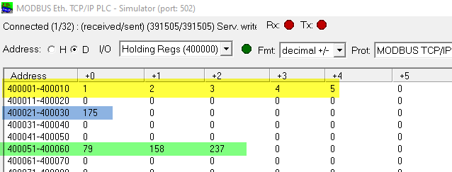
The following are the emulator registers in real time being displayed for this project.
Holding Registers 400001d - 400005d are the values to be READ FROM the Slave (Function Code FC-03).
Holding Register 400021d is the single value WRITTEN INTO the Slave (Function Code FC-06).
Holding Registers 400051d - 400053d are the multiple values WRITTEN INTO the Slave (Function Code FC-16).
Closing Comments
Additional features like edge triggered enabling are available.
Help can be found at Modbus Help
For Modbus errors, this may be helpful Modbus Errors