EtherNet/IP Scanner - Implicit Mode
EtherNet/IP uses implicit messaging, sometimes called I/O messaging, for time-critical applications such as real-time control. Implicit messaging is often referred to as I/O messaging because it’s frequently used for communication between a controller and remote I/O.
It’s a much more efficient communication connection than explicit messaging as both the client and server ends are pre-configured to know implicitly or exactly what to expect in terms of communication.
Real-time, implicit messaging basically copies data with minimal additional information built into the message. Each end of the communication link doesn’t need to be told much about what the information is for as the data has been predefined. The meaning of the data is “implied” or “implicit” so there is no extra baggage because both ends already know exactly what each bit and byte mean.
Note
Explicit messaging utilizes the UDP protocol and is typically used for continuous updating of data packets in time critical client/server communications.
Project Scope
This project will setup an ENIP Master or Scanner on the P2CDS-622 talking to a Raspberry Pi that is configured as the target or Adapter.
We will utilize the two explicit commands- Get_Attribute_Single to access data in the server and Set_Attribute_Single to control a variable in the Adapter.
This project will demonstrate:
Adding a EtherNet/IP Master fieldbus to the project.
Configuring the fieldbus parameters for connection.
Example program code that will write and read access a servers/slave’s Object in Explicit Connected Messaging mode.
Illustrate the normal operation visual aspects.
The objects within the Server we will access are the Identity Object (Class 0x01h) and the Assembly Object (Class 0x04h).
The IDENTITY Class Object (0x01h) is defined as follows:
- Instance
Identity - ID 0x01h
- Attributes
Vendor ID - ID 0x01h
Device Type - ID 0x02h
Product Code - ID 0x03h
The ASSEMBLY Object (0x04) is defined as follows:
- Instance
Output Buffer - ID 0x64h
Input Buffer - ID 0x65h
- Attributes
Get/Set - ID 0x03h (which is not used in this project).
- Services
Get Single - ID 0x0Eh (which is not used in this project).
Set Single - ID 0x10h (which is not used in this project).
Create/Import the Scanner P2CDS-622 Project
Caution
To do this project, the steps outlined in the previous section Preparation have to be completed successfully.
Two projects are provided in an Archive format. One is the Scanner or Originator that will run on the P2CDS-622 and the Adapter that will be hosted by a Raspberry Pi unit.
This Scanner project is downloadable in an *Archive* format- ENIP Implicit Scanner project
It is the Scanner or Originator that will run on the P2CDS-622.
The Adapter or Target is provided also for reference and was run on a Raspberry Pi 4 Model B using an evaluation license from CODESYS that can be found here https://us.store.codesys.com/codesys-control-for-raspberry-pi-sl.html.
The downloadable RPi Adapter project is here- RPI Adapter.
Start CODESYS and Create a Project
Start CODESYS
(1). Start CODESYS from the Start menu (by default, the path is Programs > CODESYS (version).
You can also click the CODESYS icon that is located on the desktop after installation.
Import the project
Tip
If you want to start a project from scratch, do not import the projects and just follow the steps after the Import.
(2). With CODESYS IDE launched, click File > Project Archive > Extract Archive. Select all options in pop-up. Click “yes” on next pop-ups.
Update everything (including Library’s) to latest revisions. You may need to add a Library, e.g. Basic OSCAT.
Your Project Tree view should look something like the image below with the Name of your project and the associated Device (P2CDS622) as the target.
The default Base (P2-04B) is inserted in the tree with no modules added yet, i.e. <Empty>. If your hardware topology is a different Base, see the section below on changing the Base type.
The elements of the project tree can be investigated further by going to the Help section online by pressing <F1> in the device tree area and searching for a specific item of interest.

Project Comments
Tip
The following steps are for a guide to show you how to create your own project in lieu of the completed Demo project.
Network Configuration “NetConfig”
(3). Setup Ethernet ports by adding the NetConfig functionality per NetConfig Device
Fieldbus Comm Port: “Ethernet”
The first step in adding the ENIP fieldbus is to instantiate an Ethernet port, assign it to the applicable P2CDS-622 port.
Ethernet Port: Add Device > Fieldbus > Ethernet Adapter > Ethernet
Assign IP Address: Ethernet > General > Browse
The edits that are required are as follows:
Under the General tab, select the applicable Ethernet port out of the P2CDS-622. The IP address should match the expected.
EtherNet/IP Originator: “EtherNet_IP_Scanner”
Next the ENIP Master/Scanner is added.
(4). Right click on Ethernet: Add Device > Fieldbus > EtherNet/IP Scanner > EtherNet/IP Scanner
The edits that are required are as follows:
(use defaults)
EtherNet/IP Target: “Generic_EtherNet_IP_device”
The Generic adapter will be added. NOTE: if you have the connected device/adapter’s EDS file it can be imported into the Device Directory and then added in lieu of “generic”
(5). Right click on Ethernet_IP_Scanner: Add Device > Fieldbus > EtherNet/IP Remote Adapter > Generic EtherNet/IP device
The edits that are required are as follows:
Under General tab, assign the IP Address that corresponds to the connected Adapter.
Under the Connections tab, add a connection that looks like the following (these define the Assembly IDs for the Scanner and Adapter):
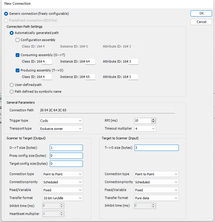
This “connection” will now show up in the Assemblies tab and you can name accordingly.
In the EtherNet/IP I/O Mapping tab section, variables are assigned to these IOs.
Program “PLC_PRG”
The program is very simple- Scanner output variables are set to values to send out and Adapter input variables are received.
Create/Import the Adapter Raspberry PI Project
The second project is the Adapter or Target and is provided also for reference. It is targeted for the Raspberry Pi 4 Model B using an evaluation license from CODESYS that can be found at RPi License
Start CODESYS and Create a Project
(As in the above example)
Fieldbus Comm Port: “Ethernet”
The first step in adding the ENIP fieldbus is to instantiate an Ethernet port, assign it to the applicable P2CDS-622 port.
Ethernet Port: Add Device > Fieldbus > Ethernet Adapter > Ethernet
Assign IP Address: Ethernet > General > Browse
The edits that are required are as follows:
(6). Under the General tab, select the applicable Ethernet port out of the P2CDS-622. The IP address should match the expected.
EtherNet/IP Target: “EtherNet_IP_Adapter”
Next the ENIP Target/Adapter is added.
(7). Right click on Ethernet: Add Device > Fieldbus > EtherNet/IP > EtherNet/IP Local Adapter Scanner > EtherNet/IP Adapter
The edits that are required are as follows:
(use defaults or General can be modified as desired)
EtherNet/IP Target: “Generic_EtherNet_IP_device”
The Generic adapter will be added. NOTE: if you have the connected device/adapter’s EDS file it can be imported into the Device Directory and then added in lieu of “generic”
(8). Right click on Ethernet_IP_Adapter: Add Device > Fieldbus > EtherNet/IP > EtherNet/IP Module > EtherNet/IP Module
The edits that are required are as follows, under the “Assemblies” tab:
The Consuming Assembly (Scanner data –> Adapter) with Object ID of 0x64h. One(1) variable, single byte.
The Producing assembly (Adapter data –> Scanner) with Object ID of 0x65h. Three(3) variables, single byte.
Additional items could be added if desired.
In the “EtherNet/IP Module I/O Mapping” tab, variables have been assigned to the respective assembly.
Program “PLC_PRG”
The program that has been provided takes reads in the Scanner data ( bMotor_VoltSet ) and writes out to the Scanner the three bytes
( bTemperature_Motor11-3 ).