Modbus
The Modbus fieldbus modes included with the P2CDS-622 system are the Modbus TCP Master, TCP Slave, RTU Master and RTU Slave topologies.
Introduction
The section overviews the solutions available, their capabilities and references some specific example projects.
The two physical interface modes are the TCP, which utilizes the Ethernet ports for the physical communications channel and the RTU mode which uses either the RS-232 or RS-485 serial ports as the communication connection.
General Specifications
Modbus TCP Client can support: 32 Slaves
Modbus RTU Client can support: 32 Slaves
Modbus TCP Server can support: 16 Connections
Modbus RTU Server can support: 1 Connection
Note
All the Modbus device libraries are included free in the P2CDS-622 system. The license is automatically enabled.
The CODESYS Modbus TCP- Master Datasheet can be downloaded from- TCP Master
The CODESYS Modbus TCP- Slave Datasheet can be downloaded from- TCP Slave
The CODESYS Modbus RTU- Master Datasheet can be downloaded from- RTU Master
The CODESYS Modbus RTU- Slave Datasheet can be downloaded from- RTU Slave
Function Codes, Addresses and Data Types
The following are the operational Function Codes (FC) supported, the applicable Address Range where they may reside (can be custom assigned) and the type of Data these FC’s support.
FC |
Name |
Addressing |
Operation |
Data Type |
|---|---|---|---|---|
01 |
Read Coils |
00001 - 09999 |
Read |
Byte/Bool |
02 |
Read Discrete Inputs |
10001 - 19999 |
Read |
Byte/Bool |
03 |
Read Holding Register |
40001 - 49999 |
Read |
Word (16 bits) |
04 |
Read Input Register |
30001 - 39999 |
Read |
Word |
05 |
Write Single Coil |
00001 - 09999 |
Write |
Byte/Bool |
06 |
Write Single Register |
40001 - 49999 |
Write |
Word |
15 |
Write Multiple Coils |
00001 - 09999 |
Write |
Word |
16 |
Write Multiple Registers |
40001 - 49999 |
Write |
Word |
23 |
Read/Write Multiple Registers |
40001 - 49999 |
Read/Write |
Word |
Modbus TCP
The TCP topology utilizes the standard Ethernet Adapter supporting both the Modbus TCP Master configuration and the Slave/Device topology.
This configuration is dependent on the Modbus library device selected.
Detailed features and of how to use the Modbus TCP version of the stack are given in an example project in Section Modbus TCP Project
The Modbus TCP protocol uses a Client/Server architecture for data exchange.
Clients are devices that initiate any data exchange with other devices on the network, i.e. Masters. This applies to both I/O communications and service messaging.
Servers are devices that address any data requests generated by a Client. This applies to both I/O communications and service messaging.
The communication between the Modbus TCP IOScanner and the slave device is accomplished using Modbus TCP Channels.
TCP Master
The communication parameters are predefined in the configurator, such as the IP Address and port number settings of the Ethernet Adapter.
Modbus commands are defined in the Configurator and are oriented to a specific Modbus slave. The commands can be processed by the device at predefined intervals, or can be triggered programmatically. For predefined commands, I/O channels are generated automatically with variables that can be mapped (I/O mapping).
The following link provides a project example- Modbus TCP Project.
Master Configurator
The CODESYS Modbus TCP Master configurator defines the Modbus commands and are targeted to a specific Modbus slave.
The commands can be processed by the device at predefined intervals, or can be triggered programmatically.
For predefined commands, I/O channels are generated automatically with variables that can be mapped (I/O mapping).
The CODESYS Modbus TCP Master configurator consists of editors for the following device categories that are inserted into the device tree hierarchy:
Ethernet: The Ethernet adapter is configured here (IP address, subnet mask, etc.)
Modbus TCP Master: A Modbus TCP master can be inserted below the Ethernet node. Communication settings can be defined specifically for Modbus, for example “Response Timeout” for defining the time to wait for a response from a Modbus TCP slave.
Modbus TCP Slave: Multiple Modbus TCP slave devices can be inserted below a Modbus TCP master. The slave address is defined here, as well as a series of Modbus commands (incl. respective I/O mapping). These are processed by the driver and exchanged with the Modbus TCP slave.
The following is an example of the Master Configurator for the TCP mode within the tool.

Creation of Modbus commands, as shown below can be defined so that they are created automatically when devices are inserted into the project.
The example projects located here at (Modbus TCP Project and Modbus RTU Project) go into detail on how to implement the commands.
TCP Slave
The PLC can also be configured as a Modbus Slave device using the TCP Slave fieldbus.
Modbus RTU
Modbus RTU is an open serial protocol derived from the master/slave architecture (now client/server) originally developed by Modicon (now Schneider Electric). It is a widely accepted serial level protocol due to its ease of use and reliability.
Modbus RTU messages are a simple 16-bit structure with a Cyclic-Redundant Checksum. The simplicity of these messages ensures reliability. Due to this simplicity, the basic 16-bit Modbus RTU register structure can be used to pack in floating point, tables, ASCII text, queues, and other data.
The RTU topology utilizes the Serial Comm ports (RS-232 or RS-485) for the physical connections.
RTU Master
The communication parameters are predefined in the configurator, such as the settings of the Comm ports (baud rate, port number).
Modbus commands are defined in the Configurator and are oriented to a specific Modbus slave. The commands can be processed by the device at specific intervals, or can be triggered programmatically. For predefined commands, I/O channels are generated automatically with variables that can be mapped (I/O mapping).
Processing requires a protocol stack and CODESYS I/O driver that implements Modbus communication on the configured port. This I/O driver is supplied with the license with the P2CDS-622 package.
The CODESYS Modbus RTU Master is configured completely from within the CODESYS Development System.
The following link provides a project example
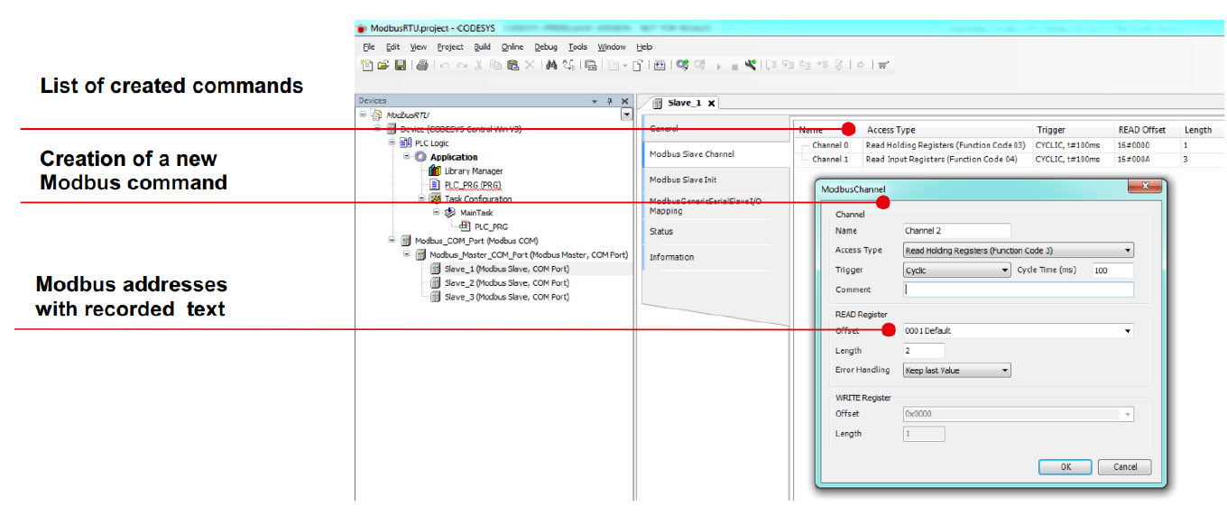
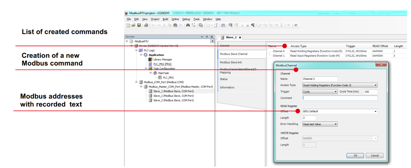
Master Configurator
The CODESYS Modbus Master (RTU) configurator consists of editors for the following COM port device categories that are inserted into the device tree hierarchy:
Modbus: The COM port settings are configured here, such as baud rate and parity.
Modbus Master: A Modbus master can be inserted below the COM port.
Communication settings can be defined specifically for Modbus RTU, for example “Response Timeout” for defining the time to wait for a response from a Modbus slave.
Modbus slave: Multiple Modbus slave devices can be inserted below a Modbus master. The slave address is defined here, as well as a series of Modbus commands (incl. respective I/O mapping). These are processed by the driver and exchanged with the Modbus slave.
Creation of Modbus commands can be defined to use that are created automatically when devices are inserted into the project as shown below.
RTU Slave
The PLC can also be configured as a Modbus Slave device using the Modbus Serial Slave fieldbus.
Example Projects
Examples projects a located at these links for Modbus TCP and for Modbus RTU