Physical Ports
The P2CDS-622 CPU is provided with several Communications Ports. A detailed description of each of these ports are in the sections below.
The Communication Ports are:
Item # |
Communication Port |
|---|---|
1 |
MicroSD Card |
2 |
USB-C Programming Port |
3 |
RS-232 or RS-485 Serial Port (RJ12) |
4 |
RS-485 or RS-232 Serial Port (TBLK) |
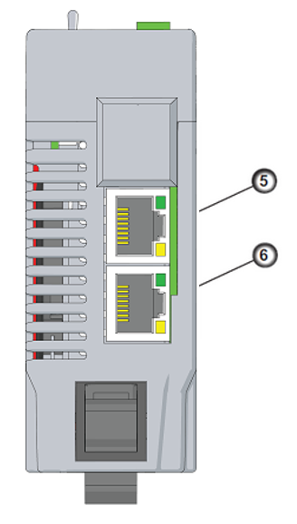
5 |
10/100 MB Ethernet Port #1 |
6 |
10/100 MB Ethernet Port #2 |

Micro SD Card/Unmount Button
The SD Card can be used for Data Logging in the project.
When an SD Card is inserted, the “uSD” LED will flash green a few times then stay on steady green.
The “Unmount” button is pressed prior to removing the SD Card. When pressed, the uSD LED will flash momentarily during the unmounting process. When the uSD LED turns off, this indicates it is safe to remove the SD Card.

USB-C Programming Port
This is a standard USB-C Slave input for programming and online monitoring, with built-in surge protection.
The transfer rate is 480Mbps.

LINK - USB connection status. Green LED illuminated when connected (LINK established).
RS-232/RS-485 Serial Port (RJ12)
The RJ-12 connector is shown below and supports RS-232 or RS-485 communications (programmable in the IDE) and is detailed in the section CPU Communications under Serial RS-232/RS-485.

This port can be used for:
Modbus RTU Master Connections
Modbus RTU Slave Connections
Modbus detail functionality is covered in the Modbus Section.
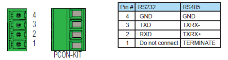
RS-485/RS-232 Serial Port (TBLK)
The 4-position Terminal Block shown below supports RS-485 communications and is detailed in the section CPU Communications under Serial RS-232/RS-485.
This port can be used for:
Modbus RTU Master Connections
Modbus RTU Slave Connections
Modbus RTU detail functionality is covered in the Modbus Section here- Modbus.
10/100 MB Ethernet Port (x2)
The Ethernet ports are based on 10/100Base-T Ethernet with an RJ-45 style connector.
This port can be used for:
Connection to a PC running the CODESYS Suite Development System.
Modbus TCP Client connections (Modbus requests sent from the CPU).
Modbus TCP Server connections (Modbus requests received by the CPU).
EtherNet/IP Scanner (32 Adaptors)
EtherNet/IP Adapter (4 scanners) with 8 connections per device.
MQTT protocol
Outgoing Email
WebVisu enabled HMI
Ethernet Port Configuration detail in Ethernet.
Modbus TCP detail functionality is covered in the Modbus Section- Modbus.
EtherNet/IP detail functionality is covered in the EtherNet/IP Section- EtherNet/IP.