Ethernet
There are two 10/100MB Ethernet ports on the P2CDS-622 that need to be setup via the USB port before the Ethernet ports can be used.
This chapter discusses how to setup the ports in the CODESYS IDE.
The P2CDS-622 Ethernet Ports support different two different operating modes:
- 1). Information Technology (IT) Mode:
LANs with access to Internet
Default Gateway only allowed to be setup here.
Recommended applications- MQTT, WebVisu, etc.
- 2). Operational Technology (OT) Mode:
Internal (non-Internet) networks
Default Gateway is not applicable
Recommended applications- on premise or local device like EtherNet/IP, Modbus TCP, etc.
Note
Ethernet Port 1 (ETH1) is dedicated to only the IT mode, while ETH2 is dedicated only to the OT mode.
Introduction
The NetConfig setup utility will be used in this configuration process.
The Ethernet ports are located on the bottom of the CPU, ETH 1 is located toward the front of the faceplate.
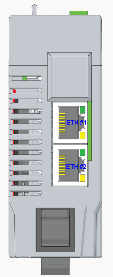
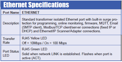
The specifications and functionality are listed below.
The pinout of the connectors are as follows:

The following sections will define how to configure the Ethernet ports in the CODESYS IDE.
Tip
There is automatic crossover detection of which cable is inserted, so either cable will work.
System Requirements and Installation
- This section requires the following:
P2CDS-622 CPU
P2000 Base (any variant)
P2000 Power Supply (any variant)
Latest version of CODESYS installed on Host PC
USB TypeC cable
Initial Network Setup
Caution
To do this section, the steps outlined in the previous section Preparation have to be completed successfully.
Host PC to P2CDS-622 connection
To get a baseline on the Host PC Ethernet connections you have on your Host PC, go to the “Network and Sharing” section of your OS and note the Ethernet connections that are present.
We are going to use the “Virtual Ethernet over USB (RNDIS)” feature in the P2CDS-622 to use the USB communications port to setup the device’s Ethernet ports.
First we want to verify the P2CDS-622 is on the network and can be seen by the Host PC.
P2CDS-622 onto the Network (via USB)
(1). With the P2CDS-622 powered off, connect the Host PC USB port to the P2CDS-622 front panel USB-C.
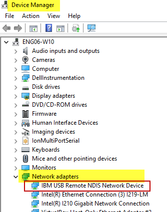
(2). Power-up the P2CDS-622, and note in the PC’s “Network and Sharing” that a new Ethernet connection (P2CDS-622 Ethernet) is present. This is the USB port of the P2CDS-622.
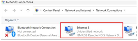
We are not connected to the P2CDS-622 with the CODESYS IDE yet, but we want to make sure the PLC can be seen on the network.
Create a Project
We need to create a project and add the device (P2CDS622_NetConfig) that will allow the Ethernet ports to be setup.
Start CODESYS and Create a Project
Start CODESYS
(3). Start CODESYS from the Start menu (by default, the path is Programs > CODESYS (version).
You can also click the CODESYS icon that is located on the desktop after installation.
Create the project
(4). Click File > New Project
The example project here will be named “TestGenlItems”
(5). In the New Project window, in the Templates section, select the Standard Project template.
(6). Specify a name and a storage location for the project and click OK
(7). In the Device drop-down location, select the P2CDS622 device.
(8). In the PLC_PRG in drop-down location, leave default values.
Add the “P2CDS622_NetConfig” Device
(9). Right-click on Device (P2CDS622) in the device tree and select Add Device.
(10). In the pop-up under Miscellaneous, select P2CDS622_NetConfig as shown below.
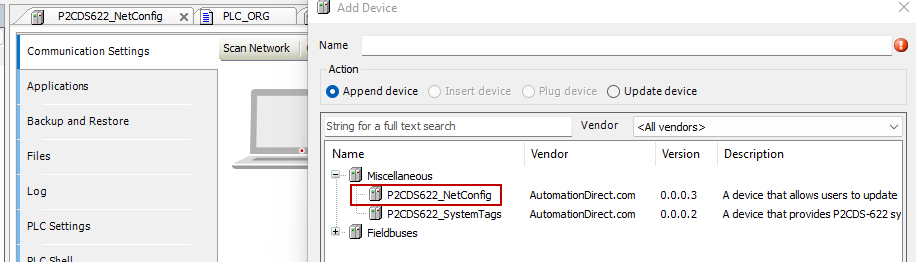
It now appears in the Device Tree and will be edited.
Configure the Ethernet Ports
“NetConfig” Device
The NetConfig device is an interface to enable the User to define the Ethernet Port’s IP Address, Subnet Mask, DHCP mode, etc. Both Ethernet ports on the P2CDS-622 can be configured in this area.
Note: This device is not associated with any System I/O or Fieldbuses, but is just used as a configuration “tool”

Caution
The Ethernet ports are independent and must operate on separate networks.
Internal Parameters
(11). To view the setup parameters, Click on P2CDS622_NetConfig and the following should be seen.
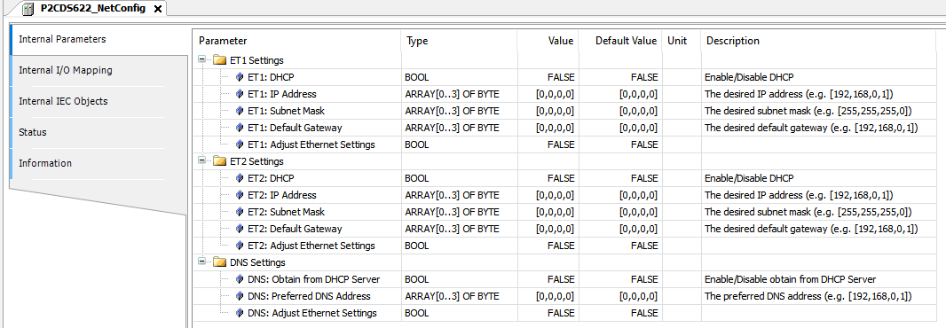
To setup Ethernet Port #1 (ETH1), follow the steps below.
Note that whenever you want to modify a parameter, you need to set the Adjust field to TRUE for the first download. After that, the profile is saved and it is recommended you set the Adjust field to FALSE so it is not continually rewritten.
(12). Edit the applicable fields under the Value column.
Setup DHCP IP Address Mode
“ETH1: DHCP” > TRUE
“ETH1: IP Address” (n/a)
“ETH1: Subnet Mask” (n/a)
“ETH1: Default Gateway” (n/a)
“ETH1: Adjust Ethernet Settings” > TRUE
Setup Fixed IP Address Mode
“ETH1: DHCP” > FALSE
“ETH1: IP Address” > (set to Address desired, e.g. [192,168,5,25]
“ETH1: Subnet Mask” (set to Mask desired)
“ETH1: Default Gateway” (set to Gateway desired)
“ETH1: Adjust Ethernet Settings” > TRUE
Setup DNS Settings
“DNS: Obtain from DHCP Server” > (enable/disable)
“DNS: Preferred DNS Address” > (set to Address desired)
“DNS: Adjust Ethernet Settings” > TRUE
The Ethernet ports are now ready to be used to connect to the CODESYS IDE or be utilized to add an Ethernet connected fieldbus like Modbus TCP or EtherNet/IP.
Note
To reiterate, whenever you want to modify a parameter, you need to set the “Adjust…” field to TRUE for the first download. After that, the profile is saved and it is recommended you set the “Adjust…” field to FALSE to not be overwritten on subsequent downloads.
Verify Ethernet Settings
This section will show you how to see what the actual port parameters are based on your settings. For example if DHCP was chosen, you can see what the assigned Ethernet address.
Connect to PLC and Download Project
The project needs to be downloaded to the target and until now, we have not connected to it.
(13). In the Device Tree, Double-click on the Device(P2CDS622).
A Device tab should appear with the first tab on the left selected entitled Communication Settings selected. Now we need to scan the network to find our device.
(14). In the Communication Settings section, click on the Scan network.
A dialog box should pop up with all the CODESYS PLCs available to connect to on this network.
Tip
If you are unsure which unit is the one you want to connect to, on the right side is a Wink select box. Click on this and this P2CDS-622 front panel RUN light should start to flash for 5 seconds.
(15). Select the applicable P2CDS-622 unit and Click OK.
Now the following should be visible. Both the Gateway and the P2CDS-622 should have the green indicators present indicating the CODESYS IDE is connected to the P2CDS-622.

Download Application to PLC
(16). Click Online > Login.
If there is an existing application on the PLC, a dialog opens up. Click Yes to continue.
The Project is now in the PLC.
(17). Click Online > Logout to disconnect.
(18). Remove the USB cable.
Connect to PLC via the Ethernet Port
(19). Plug in Ethernet cable to the ETH1 port.
(20). In the Communication Settings section, click on the Scan network and connect to the PLC (this may take several seconds).
Inspect the Ethernet Port Settings
(21). Login to the PLC. Click Online > Login.
(22). Verify the setup parameters, Click on P2CDS_622_NetConfig. The parameters should be visible under Current Value.
If they are satisfactory, you are good to go. If not, logout, edit NetConfig and repeat the process.
Ethernet Applications
The two communication applications that can be run on the Ethernet Ports simultaneously are Modbus-TCP and EtherNet/IP.
Modbus TCP
Refer to this section Modbus for detail information.
EtherNet/IP
Refer to this section EtherNet/IP for detail information.